INTRODUCTION
The PCB layout module of the Proteus Design Suite and offers netlist based PCB design complete with a suite of high performance design automation tools.
Proteus Version 9.xx is officially compatible with Windows 11 and later.
Layout Editor Features
Major features of the Proteus Professional Layout Module include:
- 64 bit high-precision database giving a linear resolution of 10nm, an angular resolution of 0.1° and a maximum board size of +/- 10m. Proteus supports 16 copper layers, two silk screens, two assembly, eight mechanical layers plus occupancy, slot, solder resist and paste mask layers.
- Hardware accelerated display (Direct2D or OpenGL) using the power of your graphics to improve speed and provide true layer transparency.
- State of the art ergonomic user interface with modeless selection, selection and activity indicators and localised functionality via context menus. Objects can be grouped so that they move and place as a single unit, and a dedicated Measure Mode reports distances between objects on the board.
- Live netlist and shared database binding with the Schematic capture module, including the ability to specify routing information on the schematic.
- Thousands of library parts included as standard and a universal Library import tool supporting all the major part vendors to provide countless more in on demand.
- Complete user control of layer stackup and drill passes. Smart vias make use of legal drill ranges, and high density interconnect (HDI) boards are catered for with through, blind, buried and micro-via drill spans plus via-in-pad construction.
- Live Physical Design Rule Checker and Connectivity Rule Checker. Uses comprehensive design rule priority system, including design rule rooms on the board.
- Powerful push and shove route placement and route editing features, track necking, length matching, dynamic teardrops and curved trace support.
- World-class adaptive shape based autorouter capable of achieving completion on even the most complex of boards.
- Template and Technology Data scheme allows for flexible re-use of board outlines and design constraints.
- Automatic net tuning and serpentine creation to length match high speed lines. Includes specification of internal lengths in components.
- Dedicated support for differential pair routing and configuration, including automatic skew correction and visualisation.
- Fully automatic Back-Annotation of component renumbering, pin-swap and gate-swap changes.
- Full support for design re-use through schematic & layout project clips (design snippets).
- Output to a wide range of printers and plotters including the Valor ODB++ format, Gerber X2 and traditional Gerber/Excellon. Also output in DXF, PDF, EPS, WMF and BMP graphics formats, to file or clipboard where appropriate. The Output Job Manager gathers the outputs a design needs into named jobs which are stored with the project and can be regenerated in a single operation.
- Built in Gerber Viewer and Panelizer: these enable you to check your Gerber output files before spending money on bureau fees or board manufacture. The Pre-Production Check runs a series of tests over the design to detect common manufacturability problems, and can be run automatically as part of an output job.
- 3D Board Visualisation with Solidworks compatible IDF, STL outputs as well as 3D DXF and 3DS output.
Auto-Placement
Proteus includes an auto-placer and floorplanning feature, an addition which in combination with the auto-router makes it possible to create simple PCBs almost entirely automatically. Alternatively, you can use it interactively, either by pre-placing critical components manually and auto-placing the rest, or else by using it to place small sections of the design in turn with manual adjustments being made after each section is placed.
The auto-placer is highly configurable and can be set up to handle a wide variety of board types.
Auto-Routing
The most tedious, error prone and time consuming part of the traditional electronics development process is undoubtedly routing the PCB. As a result, it is in this area that the greatest benefits of Electronic Design Automation are to be found.
Our auto-router is a state of the art adaptive shape based router and you will find it capable of near 100% completion of designs that could take days by hand. It includes cost-based conflict reduction algorithms that allows the natural flow of the nets to emerge during routing and minimises both trace length and via count.
In addition, a direct interface is also available to the ELECTRA autorouter from Connect EDA.
Power Planes
Proteus layout supports Polygonal Gridless Power Planes which overcome most, if not all of the disadvantages associated with other methods of implementing copper fills. The essence of the approach is to generate polygonal boundaries around all the objects within the target area, and then to merge them together. The resultant multi-edged hole boundaries are subtracted from the original (user placed boundary) in order to establish whether or not there is complete or partial connectivity.
3D Board Visualisation
Proteus comes with a 3D Visualisation engine, allowing you to examine the board as it will appear in real life prior to prototyping. This not only assists with layout design but also provides information on height clearance. With simple, mouse driven navigation it is now the matter of a couple of mouse clicks to launch and examine your design in three dimensional space. Mechanical model import and 3D CAD output in STEP/IGES format is also supported.
High Speed Design
With the advanced feature set (PCB Level 2 or higher) users can length match tracks and tune nets quickly and easily. Either select routes and enter a target length or match a set of selected routes to each other. Differential pairs can be fully configured with pass-through components and a dedicated routing mode to manage both tracks at the same time. Both length matching and phase matching are catered for a phase visualiser will show where routing is out of phase. Quick compliance checks can take place in connectivity mode and dedicated reports are available for both diff pairs and length matched tracks.
System Requirements
Performance in Proteus is scaleable according to your computer specification. The following are the recommended minimums requirements :
- 3.5GHz multi-core x64 Intel or AMD processor.
- Graphics card supporting Direct 2D or OpenGL Version 2.0 and multi-sampling (MSAA).
- 16Gb RAM minimum
- Windows 11 or later.
In particular, note that if your graphics card does not satisfy the above requirements the software will run in Software Graphics mode. This means that display of the screen is handled by Windows and not your graphics hardware and therefore that some features of the software will not be available.
Three graphics modes are available: Direct2D, OpenGL and Software Graphics. The two accelerated modes both depend on your particular graphics card and driver, so you can experiment with changing modes at any time via the Set Display Options command on the System Menu. Software Graphics is the fallback for machines whose graphics hardware cannot support acceleration. Multi-sampling is set separately on the same form and is not implied by your choice of graphics mode.
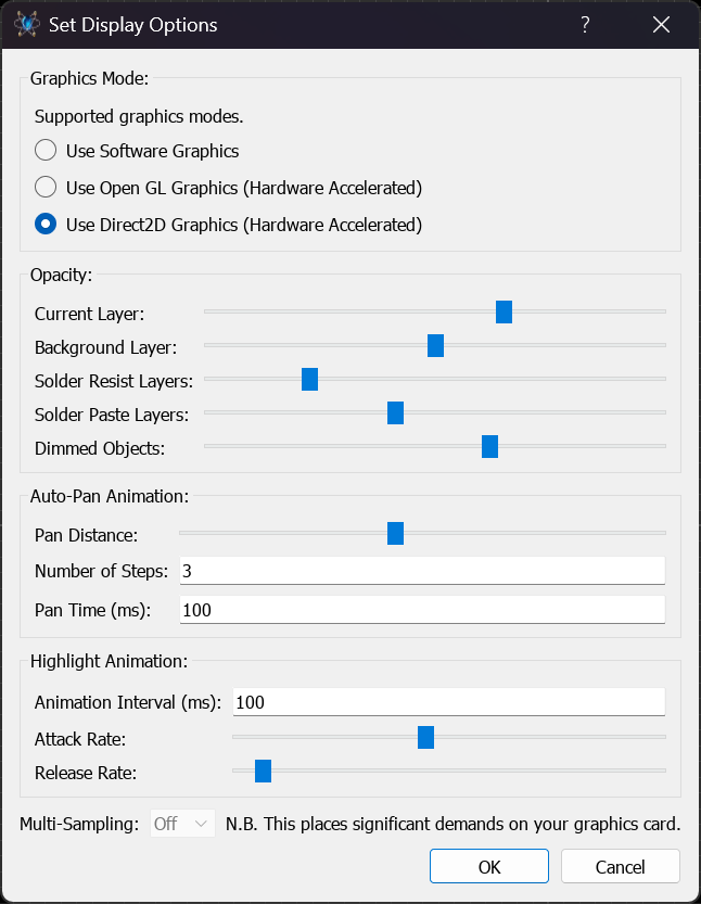
All Windows computers will support Direct2D as it is built into Windows itself.
How to use this Documentation
Whereas the getting started guides (printed documentation) contains practical summaries and tutorials, the online help serves as a reference manual for the software.
The Graphical User Interface and the general intelligence of the software itself will enable many users to be productive almost from the outset. However, as with the schematic module there is a great deal of functionality 'under the hood' and you cannot expect to master all aspects of the package immediately.
For those who need some initial tuition and guidance, we have followed the adage that the best way to learn is by doing - once you have installed the package by following the instructions in the next chapter, we suggest that you proceed to work through the extensive tutorial. This takes you right the way through the PCB design process from loading a netlist to performing the final CRC and DRC checks. You can launch this file separately from the home page (Getting Started section).
The remainder of the chapters provided background detail on all aspects of the system, and for quick reference, the final chapter deals with all the commands and any associated dialogue forms.
See Also: